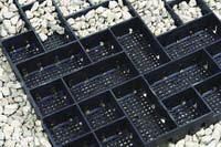
GeoPave® Porous Pavement System
The GeoPave™ Porous Pavement System with aggregate or an aggregate/topsoil engineered infill provides a permeable, stabilized surface for vehicular and pedestrian load support.
The complete system has three major components:
(1) the GeoPave® unit
(2) the porous aggregate or aggregate/topsoil engineered base, if
required
(3) the porous aggregate or an aggregate/topsoil engineered
infill.
Other components may include a geosynthetic separation / reinforcement layer between the subgrade and base materials and sub-drain components.
Function of the GeoPave Unit
The function of the GeoPave® unit is to:
1) create a structural framework to stabilize open-graded aggregate or an aggregate/topsoil engineered infill and to
2) increase bearing strength for vehicular or pedestrian traffic loading requirements using porous aggregate or other structural infills.
GeoPave®
Porous Pavement System Design & Construction Overview
[PDF Reader Required]
|
Table 1 GeoPave® Unit Material Properties & Unit Dimensions |
|
| Item | Specifications & Details |
|
Material |
Up to 97% Recycled Polyethylene* |
|
Color |
Ranges from dark shades of gray to black |
|
Chemical Resistance |
Superior |
|
Carbon Black for Ultraviolet Light Stabilization. |
1.5% - 2.0% |
|
Empty Unit Minimum Crush Strength @ 21°C (70°F) |
1,202 kPa (175 psi) |
|
Aggregate or Aggregate/Topsoil Filled Unit Minimum Crush Strength @ 21°C (70°F) |
6,869 kPa (1000 psi) |
|
Nominal Dimensions (width x length) |
0.50 m x 1.00 m (20 in x 40 in) |
|
Nominal Unit Depth |
50 mm (2 in) |
|
Nominal Coverage Area |
0.50 m² (5.38 ft²) |
|
Cells per Unit |
50 |
|
Cell Size (small cell) |
83 mm x 83 mm (3.25 in x 3.25 in) |
|
Cell Size (large cell) |
83 mm x 165 mm (3.25 in x 6.5 in) |
|
Top Open Area per unit |
90.5% |
|
Bottom Open Area per unit |
32.6% |
|
Bottom Mesh Openings |
6.35 mm x 6.35 mm (.25 in x .25 in) |
|
Nominal Weight per Unit |
3.6 kg (8.0 lb) |
|
Runoff Coefficient @ 63.5 mm/hr (2.5 in) Rainfall |
(0 - 0.15) |
|
Units per Pallet |
46 |
|
Strength Characteristics of the GeoPave Unit |
|
Empty Unit Wall Compressive Strength (simulated tire area loaded) Test Procedure - Full single unit loaded to failure via 9 inch flat plate |
1,202 kPa (175 psi) |
Aggregate or Aggregate/Topsoil Filled Unit Wall Compressive Strength (simulated tire area loaded) Test Procedure - Full single unit loaded to failure via 9 inch flat plate |
6,869 kPa (1000 psi) |
|
Avoid specifications that state material compressive strength only. Material compressive strength, with applied factors-of-safety, must be sufficient to resist compressive and lateral load application. Beyond that, ultra-high material compressive strengths add little to any porous pavement system. |
|
|
* The percentage of recycled content may vary depending on availability of recycled materials. NOTE: Dimensions and weight are subject to manufacturing tolerances (± 5%) and are influenced by recycled component characteristics. |
|
Table 2 Base Recommendations for the GeoPave® Porous Pavement System
|
LOAD DESCRIPTION |
DEPTH OF BASE |
DEPTH OF BASE |
||
|
AGGREGATE |
ENGINEERED |
|||
|
CBR1 2 – 4 |
CBR1 >4 |
CBR1 2 – 4 |
CBR1 >4 |
|
|
Heavy Fire Truck Access & H-20 Loading Typical 758 kPa (110 psi) maximum tire pressure. Single axle loadings of 145 kN (32 kip), tandem axle loadings of 220 kN (48 kip). Gross vehicle loads of 36.3 tonne (80,000 lb). |
150 mm |
150 mm |
Not |
Not |
|
Light Fire Truck Access & H-15 Loading Typical 586 kPa (85 psi) maximum tire pressure. Single axle loadings of 110 kN (24 kip). Gross vehicle loads of 27.2 tonne (60,000 lb). |
150 mm |
100 mm |
Not |
Not |
|
Utility & Delivery Truck Access & H-10 Loading Typical 414 kPa (60 psi) maximum tire pressure. Single axle loadings of 75 kN (16 kip). Gross vehicle loads of 18.1 tonne (40,000 lb). |
100 mm |
50 mm |
100 mm |
50 mm |
|
Cars & Pick-up Truck Access.
Typical 310 kPa (45 psi) maximum tire pressure. Single
axle loadings of 18 kN (4 kip).
Gross vehicle loads of
3.6 |
50 mm |
None3 |
50 mm |
None3 |
|
Trail Use Loading for pedestrian, wheelchair, equestrian, bicycle, motorcycle and ATV traffic. |
None3 |
None3 |
None3 |
None3 |
|
1 CBR is the abbreviation for California Bearing Ratio. Methods for determining CBR vary from more sophisticated laboratory methods to simple field identification methods that use hand manipulation of the soil. Presto does not recommend one method over the other, however, the user must have a high degree of confidence in the results produced by the chosen method. If other-than-CBR soil strength values exist, use available correlation charts to relate the value to CBR. 2 With the aggregate/topsoil mix and a vegetative surface, infrequent/occasional passes are recommended. Infrequent/occasional passes are defined as the number of passes over any period of time that causes no lasting damage to the vegetation. This number will be a function of vegetation type and age, climatic conditions, and maintenance practices. This number is not a function of the GeoPave material. 3 A minimum of 50 mm (2 in) of aggregate base should be placed below the GeoPave units as a drainage layer and an infiltration storage area. Greater depth may be required depending upon design rainfall needs and subbase permeability. |
||||
GeoPave® Porous Pavement System Design & Construction Overview [PDF Reader Required]
Submit Geoblock® and/or Geoweb® Project
Information:
Submit Project Information Project information will be placed in
Presto's Project Library as reference and will be considered for case studies
and/or magazine editorials.
PRESTO GEOSYSTEMS FULL PRODUCT
LINE CARD: E-BROCHURE
CUSTOMER
LITERATURE REQUESTS