Detector Loop Installation Guidelines & Technical Specifications
PART 1: GENERAL
1.1 SCOPE
A. This work consists of the installation and encapsulation of traffic detector loops in Portland Cement Concrete (PCC) and Asphalt Concrete (AC) pavements. B. The installation shall be performed in accordance with Section [Insert Local Section] of the Standard Specifications, using a high-performance, rapid-setting urethane resin system.
1.2 SUBMITTALS
A. Installation Procedures: Submit detailed protocols for production, placement, and finishing. B. Safety Data: Maintain and follow Manufacturer Safety Data Sheets (SDS) for all chemical components.
PART 2: MATERIALS
2.1 LOOP SEALER (Percol® Elastic Cement AC Grade)
The loop sealer shall be a two-component, 100% solids, rapid-setting urethane resin mixed in equal volumes (1:1).
Physical Properties:
| Property | Component A | Component B |
|---|---|---|
| Viscosity at 73°F (ASTM D2393) | 70 cps | 180 cps |
| Specific Gravity (approx.) | 1.10 | 1.03 |
| Appearance | Brown | Black |
IDOT Compliance: Detector Loop Installation Standards
Supplemental Specifications for Illinois Department of Transportation (District 1)
This work consists of furnishing and installing a Detector Loop in accordance with the requirements of Section T418 of the Traffic Specifications and revised herein.
1. Approved Sealant: Percol® Elastic Cement AC Grade
IDOT standards require a two-component, 100% solids urethane resin. Percol® Elastic Cement AC meets or exceeds all IDOT physical property requirements, providing a 10-minute cure time and superior bond strength to both asphalt and concrete substrates.
1.1 Liquid Component Properties
1.2 Cured Material Performance
2. Installation & Preparation
-
Pavement Selection: Loops must miss existing joints and cracks if possible.
-
Trenching: Saw cuts must be 1.5" minimum to 2.0" maximum deep. Width must be a minimum of 5/16".
-
Corner Treatment: All corners must be drilled with 2" cores to the depth of the saw cut. Saw cuts across corners are NOT allowed.
-
Cleaning: Use compressed air, wire brushing, and heat drying. Saw cuts must be free of debris, dust, and water residue immediately prior to sealing.
-
Wire Positioning: Detector wire must be held 1.0" below the surface using form wedges spaced no more than 18" apart.
-
Lead-in: Wire from the loop to the handhole must have six twists per foot.
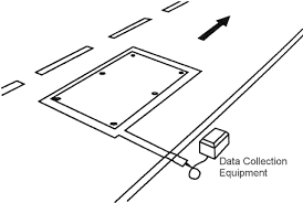
3. Engineering Inductance Formulas
Calculations must be furnished to the Area Signal Engineer at the time of inspection:
-
Single Loop (4-Sided):
-
Connected in Series:
-
Lead-In Cable:
-
Inductance Ratio: Ideal ratio of total loop inductance to lead-in is 2:1 (Minimum allowable is 1:7).
4. Final Identification & Payment
4.1 Labeling
Each lead-in wire must be labeled in the handhole using a Panduit 250W1175C waterproof tag (or approved equal) secured with nylon ties. Tags must indicate location, rotation (CW/CCW), lead-in direction, loop cable number, and number of turns in waterproof ink.
4.2 Basis of Payment
This work will be paid for at the contract unit price per lineal foot for DETECTOR LOOP, which is payment in full for furnishing, installing, and testing. Measurement is taken along the raceway in the pavement. (Note: 6' round loops may be substituted for 6'x6' square loops and are paid as 24 lineal feet).
5. Reference Standards